What Features Make a Brewhouse Easier to Operate?
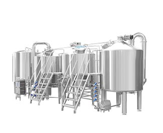
Plan a brewhouse layout by working backward from batch size, daily turns, annual output, vessel sequence, cellar capacity, cleaning cycles, utilities, and future tank additions. A 10-bbl brewhouse producing 3 turns per day needs different pipe routing, hot-water storage, drainage, and operator access from a 30-bbl system producing one turn. The Brewers Association’s 2016 benchmarking data for 26 breweries producing 10,000–100,000 bbl per year reported median water use of 5.3 bbl per packaged barrel. Floor space alone is therefore a poor sizing method. Map every product, water, steam, grain, waste, CIP, operator, and maintenance route before fixing vessel positions.
Start with production mathematics rather than a drawing. If a brewery plans to package 5,000 bbl per year from a 10-bbl brewhouse, 500 theoretical brews are required before yield losses, seasonal downtime, maintenance, and rejected beer are considered. At 2 brews per production day, brewing alone occupies about 250 days. Moving to 3 turns reduces that figure to roughly 167 days, but only when mashing, lautering, boiling, whirlpooling, cooling, hot-liquor recovery, and CIP can operate without one vessel repeatedly waiting for another.
That schedule determines whether two, three, or four brewhouse vessels make sense. A compact two-vessel arrangement may combine mash/lauter functions and kettle/whirlpool functions, while a four-vessel arrangement separates mash, lauter, kettle, and whirlpool operations. Separating functions raises equipment count and floor demand, but it also allows operations to overlap; the layout must therefore be based on the planned turn schedule rather than vessel count alone.
Draw the brewing day minute by minute before drawing equipment footprints. A vessel that waits 40 minutes for another process on every batch can affect annual capacity more than several square meters of unused floor.
Once timing is known, lay out one-direction material movement: malt receiving → milling → grist transfer → mash → lauter → kettle → whirlpool → wort cooling → fermentation. Reversing that path increases pipe length, hose crossings, operator travel, and cleaning volume. A transfer pipe with a 2-inch internal diameter holds roughly 2.0 L per meter; an unnecessary 20 m route therefore adds about 40 L of internal volume before fittings and vertical sections are counted.
That volume matters during water pushes, sanitizer circulation, product displacement, and drain-down. A brewery running 600 batches per year does not experience an extra pipe section once; it experiences it hundreds of times. Pipe routes should remain short enough for practical cleaning while leaving access to valves, pumps, flowmeters, steam traps, temperature sensors, and removable fittings.
For a smaller installation using micro brewery equipment, placing vessels close together can reduce transfer distance, but equipment should not be packed wall-to-wall. A pump may fit into a 400 mm gap during construction yet still require much more room when its motor, seal, coupling, or sanitary connections need removal. Check the service envelope supplied by the equipment manufacturer, not only the stainless-steel footprint shown on a general arrangement drawing.
| Layout item | Planning check | Why it changes floor use |
|---|---|---|
| Mash/lauter vessel | grain-out side, manway, rake service | affects operator and spent-grain route |
| Kettle | vapor outlet, heating service, access | affects ceiling and utility routing |
| Whirlpool | tangential inlet and outlet access | affects pipe orientation |
| Plate heat exchanger | plate-removal clearance | requires service space beside the frame |
| Pumps | motor and seal removal | prevents equipment blocking maintenance |
| CIP skid | supply, return, chemical access | affects cleaning pipe length |
Water and wastewater should be mapped next because brewery floors are process surfaces, not ordinary warehouse floors. Brewers Association data collected from 71 breweries for 2014 showed average water-use ratios ranging from 16.72 bbl of water per packaged bbl in breweries below 1,000 bbl per year to 4.58 bbl/bbl in breweries above 100,000 bbl per year. The association also notes that some well-performing craft breweries have operated below 3 bbl of water per bbl of beer.
A floor plan should therefore show where water actually appears: vessel washdown, hose stations, CIP returns, sampling points, keg areas, filter cleaning, pump seals, and accidental overflow. Placing one drain in the middle of a room and expecting every wet process to reach it often produces long squeegee routes and standing water. Floor slopes, trench positions, curb details, drain flow capacity, and finished equipment elevations need to be coordinated before tanks arrive.
The 2022 FDA Food Code requires food-establishment drainage systems that carry sewage to be properly designed and installed and restricts direct connections between sewage systems and drains from food-contact equipment in specified situations. Brewery requirements vary by jurisdiction, so local plumbing, wastewater, food-production, and building rules should be checked during engineering rather than after installation.
Utilities should then be placed over the process drawing. Build a simple schedule showing connection size, pressure, temperature, and expected simultaneous demand for every user rather than estimating utilities from vessel volume alone.
-
Brewing water: separate normal filling demand from peak cleaning demand.
-
Hot liquor: size storage around mash water, sparge water, cleaning, and heat-recovery timing.
-
Steam or another heating service: check peak simultaneous vessel use, not only individual equipment ratings.
-
Glycol: include cellar tanks as well as process cooling users.
-
Compressed air and CO₂: keep distribution accessible for inspection and later additions.
-
Electrical service: reserve circuits and panel space for planned pumps, controls, refrigeration, and packaging equipment.
A 20-bbl system using 1.5 bbl of hot liquor per bbl of brew length may need about 30 bbl available for one operation, while back-to-back turns can require a different storage and recovery strategy. The figure is a planning example, not a universal brewery ratio; recipes, evaporation, sparging method, heat recovery, and cleaning practice change the number substantially.
Utility routing should also leave room above the brewhouse. Vessel exhaust, steam headers, condensate return, water pipes, cable tray, lighting, ventilation ducts, fire protection, and structural beams often occupy the same ceiling zone. A two-dimensional plan can appear spacious while an elevation shows five services competing for the same 500 mm band above a platform.
Grain handling requires a separate review because milling introduces combustible organic dust. OSHA defines fugitive grain dust in its grain-handling standard as particles passing a 425-micron U.S. Standard No. 40 sieve, and its guidance notes that combustible dust should not be allowed to accumulate on exposed surfaces. Although the exact regulatory provisions that apply depend on the facility, malt milling and conveying should be reviewed by qualified safety and electrical professionals rather than treated as ordinary dry storage.
Put the mill, grist case, conveyor, bag handling, and dust-control equipment on the layout before finalizing the brewhouse platform. Moving a mill later can affect structural openings, electrical classification, duct routes, maintenance access, and malt delivery.
Spent grain needs the same level of planning on the discharge side. Ten barrels of finished wort can require several hundred kilograms of malt depending on beer strength and brewhouse efficiency, and most of that material leaves the lauter vessel wet. The grain-out door should face a cart, auger, conveyor, bin, or outside collection route rather than a narrow aisle shared with brewery visitors, chemical containers, or packaging traffic.
Cellar capacity then has to be compared with brewhouse capacity. A 10-bbl brewhouse feeding 20-bbl fermenters requires two compatible brews for each full tank. Twelve 20-bbl fermenters provide 240 bbl of nominal vessel volume, but usable production depends on fermentation time, conditioning time, headspace, cleaning, beer mix, and scheduling. Adding a faster brewhouse without enough cellar space simply moves the waiting point downstream.
The wort cooler should sit where both sides of that process remain practical. Long hot-side runs create more volume to clean before the heat exchanger, while long cold-side runs create more hygienic pipe between cooling and fermentation. If future fermenters will extend another 15 or 20 m from the current cellar, provide pipe-rack space, glycol capacity, valve locations, and a route for installing those tanks before permanent walls or packaging equipment close the path.
CIP placement should be checked against the same distances. Increasing a cleaning circuit from 25 m to 60 m increases liquid inventory and pressure loss, even when vessel size stays unchanged. Pump selection must account for pipe diameter, elevation, fittings, spray-device requirements, temperature, and the flow needed to produce the intended mechanical cleaning effect.
The platform should be reviewed from an operator’s position rather than from above. Mark every task performed during one brew: mash inspection, hop addition, sample collection, valve checks, gravity measurements, grain-out, hose connection, chemical handling, and cleaning. If an operator performs one task 6 times per shift and the layout adds a 25 m round trip, that task alone adds 150 m of walking per shift and roughly 37.5 km over 250 production days.
Maintenance requires another walk-through. Open every manway on the drawing, remove the plate heat exchanger plate pack, pull each pump motor, lift an agitator motor, access each valve actuator, and trace the route used to replace a damaged component. Equipment that can be installed but cannot be dismantled without moving a neighboring tank has insufficient service clearance.
Expansion should be tested before construction ends the exercise. Reserve a realistic position for at least the next planned vessel, utility branch, or cellar row; then confirm that a 2–4 m diameter vessel can physically reach that location through available doors, roof openings, or removable wall sections. Confirm lifting access as well. Empty floor area has limited use when a future tank cannot enter the building.
Finish the layout review by simulating at least three operating states on the same drawing: a normal brew day, simultaneous CIP and production, and equipment maintenance. Mark pedestrian routes, pallet or forklift travel, hoses, hot surfaces, chemical movement, drains, waste discharge, and emergency access. A 2026 Brewers Association resource program continues to treat water, wastewater, energy, solid waste, and brewery engineering as measured operating disciplines rather than separate building issues; layout work should use the same approach.